How can stay cable tension be measured?

Join the Move Solutions newsletter
Stay updated on product releases, news, and upcoming webinars.
The tension in an anchored cable is not accessible once the deck is in service. So engineers infer it, from geometry, from magnetic properties, or most often from vibration. Each route has its own error margin, and the differences between them can be quite large.
Why cable tension is an indirect measurement
A stay slowly loses force, because wires corrode, steel relaxes, piers settle and concrete decks creep. Load redistributes across the cable system over years, incrementally changing the condition of the cables and the bridge in general.
One bridge collapse in Italy made this an urgent regulatory question. At the Polcevera viaduct in Genoa, investigators found corrosion on the main stays of the section that came down. Those cables were encased in concrete rather than protected by a coating, which left the internal degradation uninspectable. We cover the details in why the Morandi bridge collapsed.
The guidelines adopted with Ministerial Decree 204/2022 now place cable-stayed bridges, suspension bridges and any span over 200 m in the category requiring special inspections. The trial period is active until 29 December 2026.
Methods used to measure cable force
There are five methods that can be used to measure the force of a cable. Only one measures it directly. The other four infer it from something the force changes.
Lift-off test
A hydraulic jack pulls on the anchorage until the wedges release. The pressure at that moment is the force in the cable.
This is the only method for measuring force that does so directly, so it is the reference for the other methods. It also needs anchorage access, a jack, a crew and usually a lane closure, so it requires a construction contractor to be employed.
Load cells
An annular load cell at the anchorage reports force for the life of the instrument, with no model sitting between the sensor and the number.
Although the accuracy of this method is excellent, retrofitting a bridge to use it is rarely an option. Fitting a load cell to a cable already tensioned means unloading the anchorage, which is rarely proportionate. On existing bridges the option is usually discarded.
Elasto-magnetic sensors
A coil wound around the cable measures the change in magnetic permeability of the steel under stress. Field applications have tracked tension through re-tensioning operations, calibrated against lift-off readings on the same cables.
The coil responds to temperature as well as to stress. And it has to go around the cable, which on a sheathed multi-strand stay is a real intervention.
Fibre optic strain sensing
Fibre Bragg gratings bonded to strands or embedded in the anchorage convert strain to a wavelength shift, and one fibre carries many measurement points. That suits a new bridge instrumented during construction. Retrofits have the same access problem as load cells.
The vibration method
An accelerometer on the cable records its response to wind and traffic. The natural frequencies identified from that record give the tension through a mechanical model.
Installing the sensor requires no traffic interruption and no heavy intervention. It is also the only method here where the measurement is trivial and the model does the difficult work.
How the vibration method works
The taut string model
A cable under tension T, with linear mass μ and free length L, has natural frequencies fₙ = (n / 2L) √(T / μ). Inverting gives T = 4μL²fₙ² / n². Identify one frequency, know which mode it belongs to, know the mass per metre and the length between restraints, and the tension follows from arithmetic.
The model assumes pinned ends, zero bending stiffness and no sag. Long stays satisfy all three closely enough to act on the result. A diagnostic campaign can report a 70% loss of force on a single stay with enough confidence to justify replacing the cable rather than re-tensioning it.
Frequency against mode index
Evenly spaced frequencies mean fₙ divided by n is constant. Plot frequency against mode index and you get a straight line through the origin.
That line does two jobs.
The first is accuracy. Fitting through several identified modes averages out the error on any one peak, and published comparisons show fundamental-frequency estimates carrying errors around 2.5% where multi-mode fits stay under 1.5% on the same cables.
The second is a validity check. When the points curve away from the line, the cable is not behaving as a taut string, and the tension from that fit should not be used. Bending stiffness lifts the higher modes above the line, so the curvature shows up at the top end first.
Measuring on two axes
A triaxial accelerometer on a cable gives two axes perpendicular to it. Each one supports an independent tension estimate, and since in-plane and out-of-plane vibration are governed by the same tension, the two numbers should agree.
When they do not, the problem is usually the setup rather than the cable. A sensor rotated relative to the cable, a cross-tie restraining one plane and not the other, or a wrong free length will pull the two estimates apart before either of them drifts far enough to look suspicious on its own.
Error sources
Three parameters dominate the error budget, and two further conditions can invalidate the model entirely.
Free length and linear mass
Tension scales with the square of the free length. A 2% error in L gives roughly 4% in T. The same 2% error in frequency also gives 4%. Linear mass enters directly, so it gives 2%.
Now compare where those errors come from. The frequency is measured to a fraction of a percent. The length comes off a drawing.
Free length is not the anchorage-to-anchorage dimension. The effective vibrating length ends where the guide pipe or the neoprene at the deck end restrains the cable, often several tens of centimetres inside the nominal anchorage. Linear mass has to include the sheathing, the filler and any external damping collar.
Where a lift-off reading survives from construction, back the effective length out of that known tension and reuse it for every campaign on the same cable afterwards.
Mode index assignment
Identifying a peak is easy. Labelling it is not.
Assign index n = 2 to a mode that is in fact the third and the tension comes out overestimated by a factor of 2.25, because the index enters the formula squared.
Constant spacing is the way out, since the interval between consecutive modes equals the fundamental. Peaks at 1.2, 1.8 and 2.4 Hz with nothing below are higher modes of a 0.6 Hz fundamental that was never excited. Long stays show this pattern often, because ambient excitation puts little energy into the first mode.
Short cables
The taut string model fails with short hangers and suspenders. Bending stiffness stops being negligible relative to tension, and string theory applied to a short thick cable produces large errors and occasionally results that are simply wrong.
Corrected formulations exist. Zui and colleagues published practical formulas accounting for flexural rigidity and sag in 1996, and Mehrabi and Tabatabai followed with an approach valid for a sag parameter below 3.1 and a bending stiffness parameter above 50. Field comparisons still show around 10% residual error from the Zui formula on cables with complex end restraints, while methods that also identify the rotational stiffness at the ends bring it under 4%.
On a short hanger, use a corrected formulation with several modes, or measure the force some other way.
Dampers and cross-ties
An external damper changes the modal frequencies of the cable it is fitted to. The effect grows with the damping coefficient and with the height of the damper above the anchorage, and the frequencies a damped stay produces do not belong in an uncorrected string formula.
Cross-ties are worse. They subdivide the cable into segments with different effective lengths in the plane they restrain, so out-of-plane frequencies may still follow the string model while in-plane frequencies no longer do. This is one of the situations the two-axis comparison catches.
Temperature and traffic
Cable force moves with temperature, through thermal expansion of the cable and of the structure supporting it. It also moves with every heavy vehicle crossing the span.
Field practice reflects that. On the Binh Bridge in Vietnam, measurements were taken between 7 and 10 in the morning, specifically to keep the thermal and vehicle contributions out of the comparison.
A campaign built for trend detection has to fix the time of day and record temperature alongside, which an environmental sensor on the same network provides.
Campaign measurement and continuous monitoring
A periodic campaign gives one number per cable per visit. A permanent installation gives a series. The difference decides what can be separated from noise.
Work on a cable-stayed bridge in Taiwan found that after removing daily and long-term temperature components, force changes larger than about ±1% could be identified with confidence. That is well below anything a twice-yearly campaign resolves.
Instrumentation density is modest. A long-term system on the Mao-Luo-Hsi Bridge uses one accelerometer per stay, mounted around 5 m above the protection tube at the deck end. The offset matters, since a sensor sitting too close to the anchorage falls near a node for several modes and records very little.
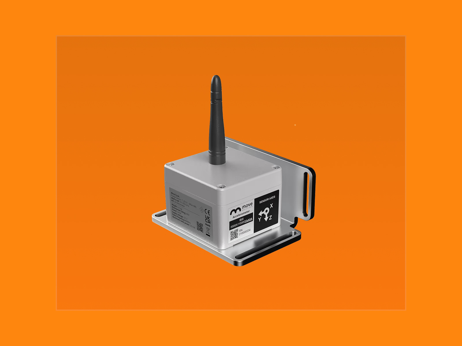
On many bridges the sensor is already up there. A wireless triaxial accelerometer installed on a stay for operational modal analysis records exactly the signal a tension estimate needs, because both start from the same identified frequencies. Our accelerometer samples between 40 and 640 Hz, which covers the higher cable modes comfortably, and those frequencies land in MyMove next to the modal work on the deck.
Adding tension to an existing bridge monitoring system is an analysis question, not a procurement one.
Choosing a method
During construction and at acceptance, lift-off is the reference and the vibration method is the fast cross-check on every cable. For an existing bridge with no instrumentation, the vibration method is usually the only proportionate option.
For long-term assessment the question changes. Accuracy matters less than repeatability.
A tension carrying 5% uncertainty from an assumed free length is still useful, as long as the same assumption applies to every measurement in the series. A constant bias leaves the trend intact, and the trend is what condition assessment reads. That is the case for a permanent network on structures where the bridge monitoring programme already exists for other reasons.
Frequently Asked Questions
Can the vibration method be used on short hangers?
Only with a corrected formulation. Pure taut string theory ignores bending stiffness, which is significant on short thick cables, so it overestimates tension. Use a formula accounting for flexural rigidity and sag, and fit it to several identified modes rather than the fundamental alone.
How accurate is a tension estimate from an accelerometer in practice?
On a long stay with known parameters, a multi-mode fit stays within a few percent of a lift-off reading. The dominant uncertainty is the effective free length, not the frequency. A cable whose restraint points are uncertain carries several percent of bias no matter how clean the spectrum is.
Does one accelerometer per cable suffice?
Yes, for tension. A single triaxial sensor a few metres from the deck anchorage identifies several modes on both perpendicular axes. Mode shape work needs more sensors. Tension only needs the frequencies.
Should tension estimates be compared against a design value?
Compare them against each other over time first. The design tension belongs to a temperature, a load case and a structural configuration that no longer exist, so the gap against it says less than a trend from the same cable measured under consistent conditions.
Do the Italian Linee Guida require cable tension monitoring?
Not by name. They place cable-stayed and suspension bridges, and any span over 200 m, in the group requiring special inspections, and the level of investigation follows from the resulting attention class. Tension measurement is one of the techniques that answers what a special inspection asks about cable condition.
Other articles


Subscribe to Updates
Stay informed about our latest innovations and insights.